Thursday 29 May 2014

Assignment 5: Submission


The process.
1) I started with a sine curve. The curve was then projected in the z direction and offset to equate the rise and fall of each line interchangeable so that an interesting modulation in the overall surface would appear.


 I repeated the process with the modulation of the vertical changes in the wall curvature. This created an interesting effect. 


2) I lofted the two curves together to create this said surface.


3) i made sure my design parameters were being met and that my object was the correct size and scale


Final Model 


Model printed however the dimensions where not correct. Printed it at 300 by 250 when the required dimensions were at 400 to 350. Will still upload model and print files. 


Grasshopper file found at:

https://www.dropbox.com/sh/ookckj4ch3vykad/AADEWBuyFDN1A2LVL7BuylX2a


Tuesday 20 May 2014

Assignment 4 Grasshopper Submission

https://www.dropbox.com/s/7dnbhv2ucpt1vra/assignment%204_start.gh

Assignment 4: The Joint


To first create a joint I needed to create a panelling system that was the exact parameters for the assignment criteria and could be solid differences with he joint to create a unique and suitable joint for that particular panel intersect.


The panelling was easily, I simply offset the rectangular parameters of a curve that bounded that parameter and found the highest point, added a lunch box node (triangular braced grid system) which gave me this interesting patter which i could later use in my laser cutting. This gave precedence for the rest of my joint design. this panelling system was constructed solely for the exhibition requirements, however below shows a more useful panelling system canopy. 

The Joint

The process. 

1) I needed to create a joint that connected the different Fasard elements in a seamless and supportive way that was appropriate for the different angels in which the panels entered the conjunction within. I also needed to make these joins parameter so that they would be easily adjusted by the user. (example panelling system). 


 These joints resolved this problem. I started by creating my voids for the curved intersection in which my joint would then fit within. The joints are triangles and are oriented n such a way as to create voids within the curve which act like teeth to grip the panels in a secure and supportive way.


I then needed to orientate the different voids onto their consecutive intersections. The height of the voids are also large to a make it easier for the user to intersect object through the panels curve. This can also be adjusted. 


The same inputs that were fed from the voids are now conversed to the joint and now become a unique joint for every intersection. 


These inputs are shared with the original voids and so parameters are adjusted accordingly and interdependent. 


Tuesday 13 May 2014

Assignment 4: The Process


For this experiment, I wanted to integrate the two different methods (3d printing and laser cutting).
My original concept was to build a canopy out of laser cut materials which would be held together by 3d printed objects


My original concept was to use a series of joints that would be unique for every individual surface. These joints would have a series of arms that would attach themselves from the surfaces of the canopy. These arms  would change angle dependent on the needs of the angle needed by the curved surface at that particular point. 


The joints would acts like a frog hand joint that is sometimes used to hold glass together.

 The placement of the points that would direct the lofting of the piping for the joints will be determined by the angle of the curved surface.


However, when I consulted my tutor on the idea, she remarked that the joints would be too weak to support the canopy. I needed a more simply adaptation for the joints which would be easy to print and assembly.


The curve that I constructed also had problems. 


I originally used a series of hexagonal shapes to divide the surface by, however this posed a number of problems such as the in planarity of the surface, made laser cutting impossible.


I used a grasshopper plugin (Lunch box) to create a triangulated grid which solved this problem. 


This made it possible for laser cutting preparation and debrepping. This same method was used for assignment 1 to laser cut my letter 'T'.


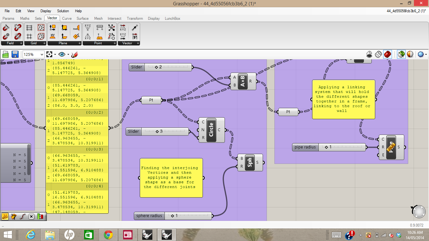
I then needed to solve this issue for the joining pieces which would eventually be solid differences from the overall curved surface.


I first debrepped the surface and used the vertices found to set a series of spheres which would be located at every joint. I used spheres as apposed to boxes because of the strength of the shape and a seamless appearance in comparison. 


The vertices used to create the spheres were then fed into another series of points which were offset from the surface in the Z direction. These two sets of points where then used to draw a set of lines. The lines were then 'piped' with the radius being a parametric value.